You have 3 free guides left 😟
Unlock your guides3.3 Steady State Circuits
5 min read•june 18, 2024
Peter Apps
Peter Apps
A circuit is a closed loop of electrical current. If the loop is open or doesn’t allow the current to return to its starting position, electricity will not flow through the circuit and any devices on that partial loop will not work. Common ways of breaking a circuit include switches or blown/removed light bulbs.
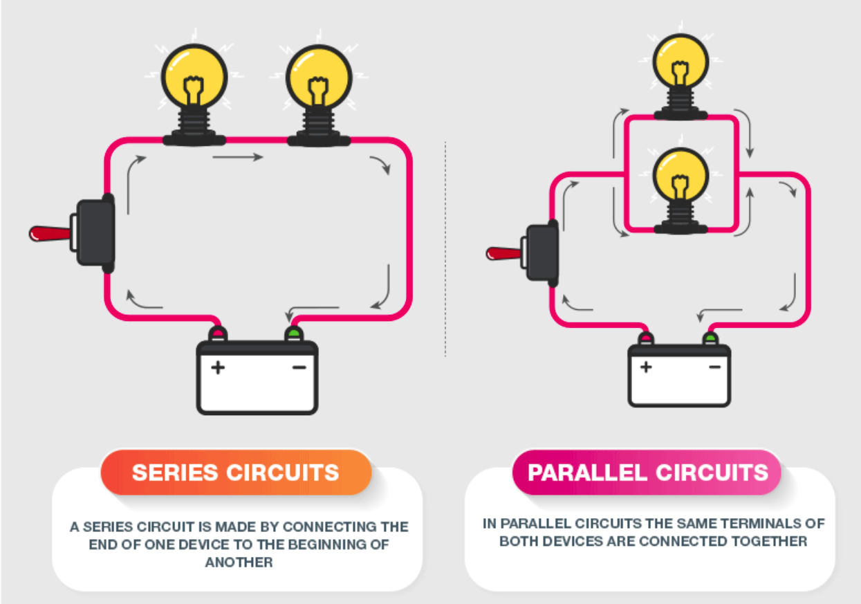
Types of Circuits (Series vs. Parallel)
Circuit components can be connected in either series or parallel. A series connection has 1 path between the components that all the current must travel through. A parallel circuit has 2 or more paths between the components. The current in a parallel circuit is split between all the available paths.
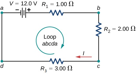
Kirchhoff's Voltage Law (Loop Rule) ➿
Kirchhoff’s Voltage Law (KVL) is used when we’re trying to analyze the current, voltage, and resistance of a circuit. The law simply states that if you have a loop in a circuit, the total voltage drop across the components and voltage source must equal 0. (Oftentimes, I’ll reword this to say that the voltage drops of the components must equal the voltage of the source).
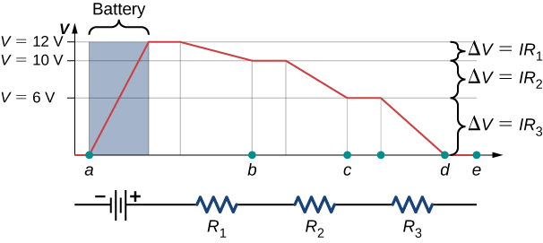
When we look at the entire circuit as a system, energy must be conserved. All of the electrical energy provided by the battery is given to the electrons (and is represented as voltage). As the electrons do work in the other components, the energy is transferred to the components and the voltage must decrease. When the electrons reach the battery again, they have completed the loop and given all their energy away.
Kirchhoff's Current Law (Junction Rule) ❌
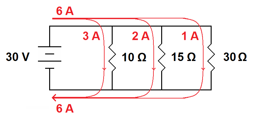
Kirchhoff's Junction Rule follows a similar logic process to the Loop Rule, except it uses conservation of charge instead of energy. In the circuit, the charge must be conserved since it’s a closed system. The current (rate of charge transfer) must be the same going into and out of a junction since there’s nowhere for the charge to disappear or appear from. In the image below, we can see that the total current (6A) is split at each junction, but the total remains the same.
Resistors in Series & Parallel
Because of Kirchhoff's rules, we can derive handy rules for resistors in series (R_s) and parallel (R_p) circuits.
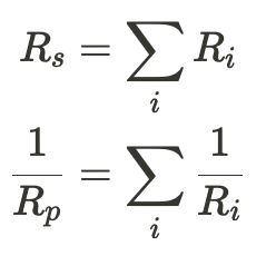
Looking at these two equations we see an interesting phenomenon. As we add more resistors in series, the total resistance increases. However, adding reduces the total resistance. An analogy that helps visualize this is relating this to check-out lanes at a grocery store. Even with the world's slowest cashier, opening another lane gets people out quicker than leaving them in a single line.
Resistivity
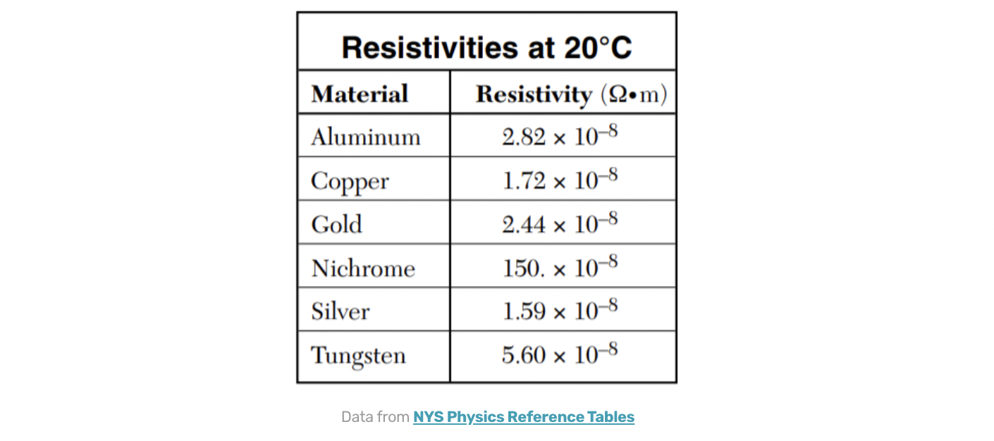
is a third way of describing the current in terms of the electric field, E, and the material it is traveling through. In this case, we define current density as a vector, J->. We then relate the electric field to the current density through the equation below. (For a full derivation of this equation, check out this link). E = ρJ. ρ is the proportionality constant between E and J and is called the . Resistivity describes how much a given material restricts the current. Resistivity depends on temperature (higher temperatures result in a higher resistivity, but most tables give values for 20 C)
Non-Ideal Batteries and EMF 🚨
As often happens with Physics problems, we idealize the 'real-world' problems away when we're doing calculations ("No air resistance", "Frictionless surface", "Ideal gasses", etc). When dealing with circuits, we tend to do this in 2 areas: wires & batteries. With wires, we assume (often correctly) that the resistance of the wires is insignificant to the total resistance of the circuit. However, with batteries, the internal resistance they exhibit is often large enough that we need to take it into account when we apply KVL and other circuit equations. This leads to us defining a new term: Electromotive Force (EMF) represented by . EMF is the total energy that can be given to a charge leaving the cell and is related to the terminal voltage by the equation
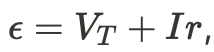
,where r is the internal resistance of the battery.

Circuit Symbols & Measuring Tools 🛠️
To easily draw circuits, we use a variety of symbols to represent common components. Here are a few common ones, and there are many many more that are not used in AP C (although if you become an electrical engineer you'll use them!)
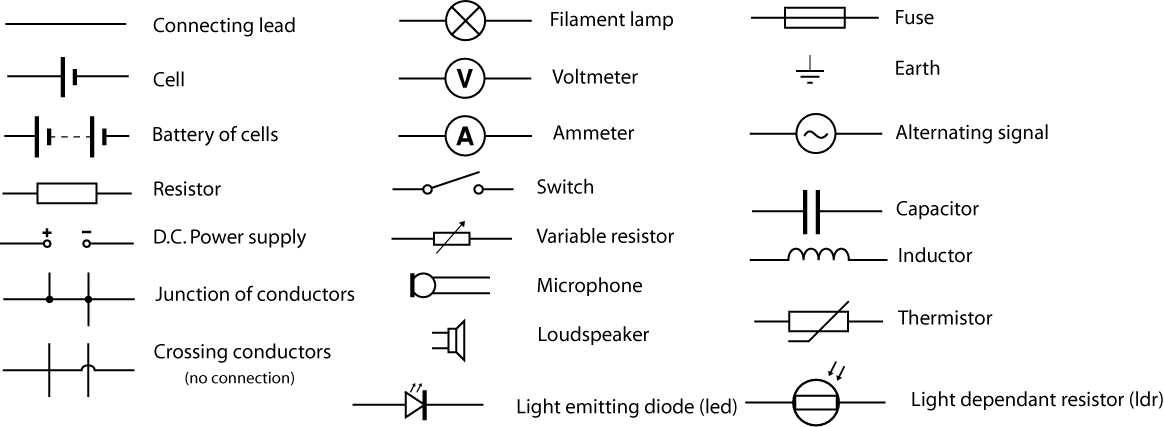
There are also two tools listed in the image above: the and the . The voltmeter is designed to accurately measure the potential difference between two points. Because of this, it is built with a very high internal resistance so as not to create a short circuit when it bridges two points in a circuit. A voltmeter is always connected in parallel around the object you are trying to measure.
On the other hand, an ammeter is designed to measure the current flowing through a part of the circuit. Because it's going to be connected in series with the component it's measuring, the internal resistance of the ammeter is designed to be very small. Hooking up an ammeter or voltmeter in the wrong configuration can lead to short circuits or a meter that doesn't function at all. Be careful in your lab experiments, and check first before you connect them.
Practice Questions:
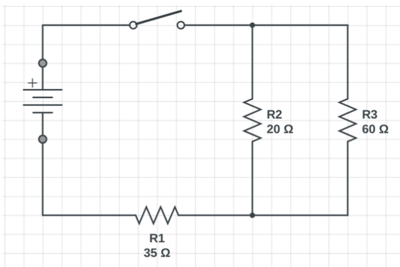
- What is the equivalent resistance of the circuit shown below
Answer
R2 and R3 are connected in parallel. Therefore, 1/R_2&3 = 1/20ohms + 1/60ohms. R_2&3 = 15ohms
R1 is in series with R2 and R3. R_eq = 35ohms + 15ohms = 50ohms.
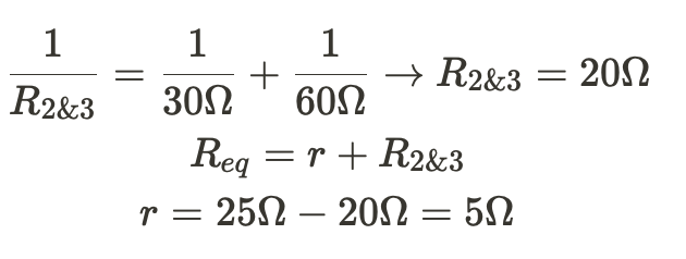
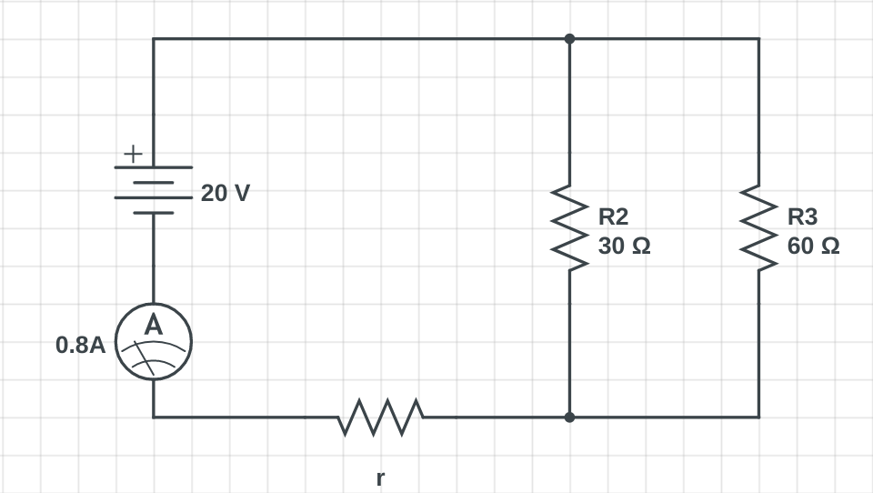
- What is the value of r in the circuit shown below?
Answer
Step 1) Find the total equivalent resistance of the circuit using
R = V / I = 20V / 0.8A = 25ohms
Step 2) Use our knowledge of resistors in series and parallel to find r